|
|
|
|
As the decade of the 1930s progressed, the United States' business and technical communities struggled on through the Great Depression. In spite of manifold difficulties in marketing to a cash-starved economy, the developing electronics industry continued to innovate as advances in technology were translated into consumer products. The smaller companies, which regularly appeared and vanished, in some instances made noteworthy contributions. One of these was RADIO CONSTRUCTORS LABORATORIES, trading as RACO PRODUCTS, which collaborated with a designer of note, A. J. Haynes, to bring out a line of regenerative/super-regenerative receivers. The 1938 RACO "Super-Clipper" first came to my attention when I located one at the 1986 AWA conference, with the idea of presenting it to readers of this column. However, the story almost died aborning, since information about the receiver seemed to be sadly lacking. However, in due course an account emerged. A. J. Haynes is documented as the designer of the first regenerative kit set (the Haynes DX Circuit, 1922, the original so-called "three-circuit tuner"), and the first |
superheterodyne
kit set in 1924 [1, 2]. In 1936 he joined forces with RACO to produce his
newest brainchild, the "R-S-R" (Regeneration-Super-Regeneration)
receiver. It was announced with great fanfare in such popular magazines
as Short Wave Craft [3], Radio-Craft [4], and Radio World
[5]. In some cases complete construction information was presented
[4, 6]. Price was $24.65, complete. A kit of parts was also available.
The R-S-R, covering the extremely wide range of 2-½ to 555 meters, was designed for the experimenter and all-wave listener "to have the entire active radio frequency spectrum literally at his fingertips.'' It was a strong inducement to be able to listen in on the increasing activity on 5 and 10 meters, the direct portable broadcasting of sporting events in the 3-4 meter range, and the new 5-10 meter experimental broadcast "Apex Class" stations (they were all located atop the highest buildings in the major metropolitan centers.) The circuit was a five-tube AC-DC layout using a mix of metal and glass tubes. On 555 to 15 meters a RF buffer was followed by a band-switched electron-coupled regenerative detector, with the 2-½ to 15 meter range covered by a super-regenerator using small plug-in coils. Haynes emphasized that both circuits must be properly designed (direct and common stage grounds and short RF leads), and that with careful adjustment the hiss level was reduced to zero and radiation minimized. |
|
|
| This
original R-S-R receiver opened the gates to a series of associated RACO
offerings. In December 1936 the 3-tube R-S-R Jr. Communication Receiver
was announced (AC, complete, ready-to-use, $12.20); also the RACO AC-4,
a 2-½ to 555 meter communication receiver without the Haynes
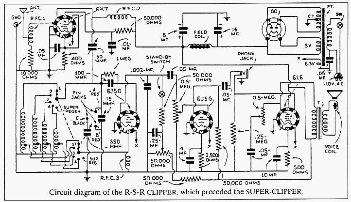
name. In January 1937, RACO announced the Haynes R-S-R CLIPPER [7], probably
the high point of the series. It was promoted in a major review article
in April [8], which gave enough information to build the circuit from scratch.
The range was 3-½ to 555 meters.
The R-S-R CLIPPER was developed from user experience with the original R-S-R circuit, with changes made in the power supply, the detector, and the audio circuits. The receiver was now an AC set: the audio tube was a 6L6 rated at 4 watts output, and a common 6J5 detector was used for the BC/HF and UHF (in Thirties terms) bands. Of note is the means of shifting over to the UHF super-regen circuit. A 3" square hard-rubber mounting plate, located in the center of the chassis, held the 15-pF tuning capacitor and three tip jacks, marked A, B, and C. For the BC/HF bands, a jumper was plugged into jacks A and C; tuning was done with the main two-gang variable, with bandspread from the 15-pF variable in the center. Bands were switched from the front panel. Moving the bandswitch to position 5 activated the UHF superregeneration circuit. The HF coils and the large tuning capacitor were switched out of the circuit, the jumper was removed, and one of the three UHF coils plugged into jacks A and B. All tuning was now done with the small variable capacitor in the center. The receiver had an appealing appearance and was priced ready-to-use at $28.85. There was no mention of a kit. |
By
September, however, the original sales boom was over and competition was
increasing, so RACO offered the R-S-R CLIPPER in kit form, assembled, ready
to wire, without tubes or cabinet, for $16.85. RACO continued to promote
such associated products as the R-9 Signal Booster and the AC-4 Communication
Receiver.
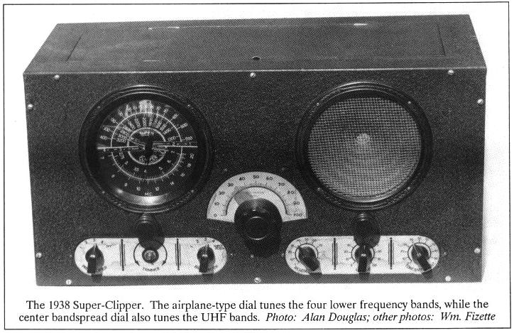
In November, another version: eight bands on the New Haynes 5-tube R-S-R CLIPPER, with a tuning range of 3 to 1600 meters. In December RACO offered the Haynes UNIVERSAL CLIPPER, an AC-DC version tuning 3 to 555 meters for $19.50, complete; and also in December, the 1938 SUPER-CLIPPER, priced at $29.75, complete [9]. The SUPER-CLIPPER featured seven bands. The tube line-up was 6K7 RF booster, 6K7 RF, 6K7 UHF RF, a common 6J5 detector, a 6J5 first audio, a 6L6 output, and an 80 rectifier. I was unable to locate a circuit, but it appears to be essentially that of the R-S-R CLIPPER, with the addition of two RF tubes and some physical changes. The UHF circuit remained the same, with three plug-in coils covering the 5-, 7.5-, and 10-meter ranges. The 20' x 10" x 9" sheet-steel cabinet is finished in the standard black crackle prevalent in 1938. On the front panel a 6" Oxford dynamic speaker is matched by the 6" "airplane" dial detailing the four lower frequency bands from 550 kHz to 20 MHz. In the center of the dial, inside the words SUPER CLIPPER, is a drawing of the 1935 Martin M-130 China Clipper style flying boat, adding to the international flavor and hype of the receiver. Along the bottom, the controls, left to right, are the preamp switch, antenna trimmer, detector bandswitch, regeneration, volume, and tone/noise controls. The on-off switch is under the speaker. The half-moon center dial is for bandspreading the lower bands and tuning the UHF ranges. In comparison with many competitive products, the front panel is attractive and well designed. |
Intense competition among the small manufacturers of these types of sets was the order of the day. While Haynes claimed to be first with the wide-range receiver, he was not alone for long. Within weeks similar products from almost next door (some competitors were even in the same building at 136 Liberty St., New York) were being advertised. Included were sets from Eilen Radio Labs and the Guy Stokely Radio Corp., |
|
 promoting
the Doerle and other circuits; Ace Radio Labs; and the Oscar B. Kusterman
Co., which took over Ellen. And the prices were very competitive. promoting
the Doerle and other circuits; Ace Radio Labs; and the Oscar B. Kusterman
Co., which took over Ellen. And the prices were very competitive.
One is struck by the scarcity of information about this receiver. After the first promotion, little else seems to have been printed. The circuit diagram, for example, is noteworthy by its absence in any of the standard reference works. If any reader happens to have a manual or any other information, the writer would |
|
| appreciate
very much receiving a copy. As for A. J. Haynes, he designed at least one
other circuit for RACO: the UHF CRUISER, advertised in June 1938. Alan
Douglas reports [10] mentioning him a few times in his books, that he lived
on Cape Cod, and that he passed on some 10-15 years ago.
The question arises: Is this a communication receiver or merely a SWL set? While the earlier R-S-R models were so listed, the SUP-ER-CLIPPER was not promoted for two-way communication use, the sales effort being directed toward the larger SWL market. However, many similar receivers, the Sargent Model 10 and 11 for example, were used for comm. work, and it would have been simple to adapt this receiver for such. My sincere thanks to Alan Douglas, Larry Rosine, Orval Parker, and the other AWA members who contributed their libraries and time to my search for background material. |
|

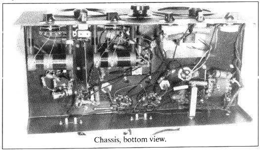
 The
photo shows the top of the chassis. The square mounting plate in the center
supports the UHF tuning components, the three tip jacks, and a trimmer.
On the rear apron are the earphone jack and the two antenna terminal strips.
The
photo shows the top of the chassis. The square mounting plate in the center
supports the UHF tuning components, the three tip jacks, and a trimmer.
On the rear apron are the earphone jack and the two antenna terminal strips.