Photofacts For Sale
Submitted by Bob Pilcher
10/20/2010
I
have several thousand of Sam's photofacts that I need to dispense
of. If the club members would like some I will make them a very
good offer (i.e 10c per folder.)
Also have many up till 1980 unopened from RCA in Camden.
Bob Pilcher RPilc99206@aol.com
Ultralight Modification
Submitted by Nick Senker
1/17/2009 Updated 01/22/09
Having been impressed by Walt Heskes' and Al Klase's modifications of
the Sony SRF59 ultralite AM/FM pocket receiver, I decided to try a
modification of my own. Both Walt and Al used a vernier
tuning dial with impressive results as the limitation of the Sony SRF59
is in its coarse tuning dial arrangement. As I don't have
such a vernier dial, I decided to check out some other options with the
miscelaneous hardware and junk components I did have.
I found an old Panasonic AM/FM 'Walkman' type with a conventional dial
cord and pulley arrangement with allows for a mechanical
reduction in the turning ratio between the tuning knob and the tuning
capacitor. This probably is not as good as a vernier dial but
should provide a significant advantage over the Sony 'direct' tuning
setup. This setup should not cause any permanent damage or
changes in the Sony circuit board and hopefully will be reversible if I
do come across a vernier dial or choose another method.
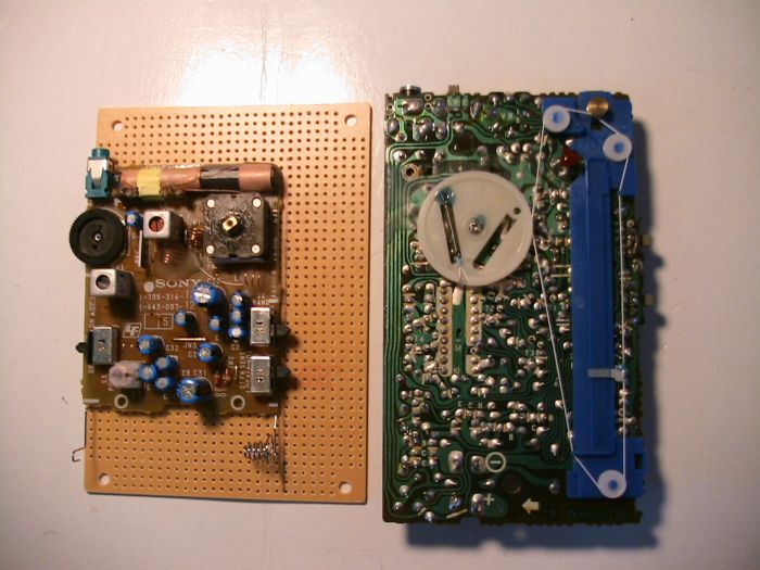
As can be seen in the photo, the Sony is disassembled simply by
removing the two small screws in the back and carefully prying the
front and back sections of the plastic case apart with a dull knife
blade. The Sony circuit board can be mounted on a small perf
board (available from 'Allelectronics.com') using the two original
mounting holes and the Panasonic pulley assembly snapped into place
adjacent to the Sony chassis. The Sony dial wheel is
unscrewed from the tuning cap and the dial pulley from the Panasonic is
mounted in its place. The larger Sony dial wheel is used in
place of the small Panasonic tuning wheel to further enhance the tuning
ratio advantage.
I am not finished with this modification yet and will supply another
photo and update when I get everything mounted but I wanted to get this
idea out there in the event others might want to try this approach or
improve upon it.
Update: 01/22/09
Well
the modification looked simple and straightforward! That's never
the case. The transfer and mounting of the Panasonic pulleys and
dial cord to the perf board went smoothly as the perf board is about
the same thickness as the Panasonic circuit board. When I put the
Sony chassis next to it however, the tuning cap extended about 1 cm
above it so the pulley height didn't match. Two choices; raise
the pulley assembly or lower the Sony chassis board.
As I had
drilled holes in the perf board and glued the pulley assembly in place,
I didn't like the idea of raising the pulley platform. I then
tried to lower the Sony chassis by cutting holes in the perf board and
mounting the Sony chassis from below in the holes. This became
very messy however and looked sloppy. Besides, the perf board was
clad on the underside and I was worried about possible shorts or at
least interference in the RF circuits.
My final solution can be
seen in the attached photo: I cut the perf board at the pulley
assembly and mounted it on a 1/2" block over a small piece of
hardboard, I then positioned the Sony chassis next to it and
fastened it with the original Sony mounting scews and a brass screw and
washer at the top. The heights of the pulleys now match and with
the right spring tension the tuning is very smooth,
I had tried
to incorporate the original Sony plastic case to accomodate the battery
but this hampered access to the switches. I therefore mounted a
separate battery holder.
The result is a significant improvement
in the tuning ability of at least two times over the original design
and it is comparable to any standard tube type radio with a dial cord
and pulley arrangement. Your comments would be appreciated.
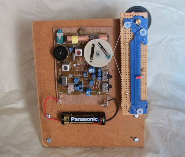
(By the way, the total assembly weighs in about 4 oz and meets our DX context requirement for Ultralight receivers)
Nick Senker n.senker@att.net
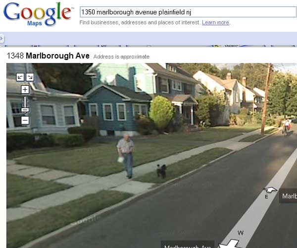
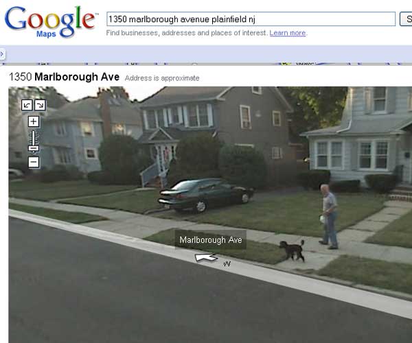
Smile, You're on Candid Camera!
Club
VP Harry Klancer was looking up directions to Ray Chase's
house on Google before heading over there. Harry clicked on the
"Street View" button on Google Maps, and when the picture came up,
Harry's wife commented that a fellow in the picture looked a lot like
Ray. On closer examination, the dog looked a lot like Ray's dog too!
Look out, Ray. It seems as if the "pooper scooper" police are
watching you!
Looking for a high quality scan
of a Radiola 20 from Dec. 4 1926 issue of Liberty Magazine
Submitted by Robert Lozier
11/8/2008
Looking for a high quality scan of a Radiola 20 ad, in color, that
appeared in the Dec. 4th, 1926 issue of Liberty magazine.
It could have also been in other publications.
It is inside a western theme ranch house with the family around a small
Christmas tree and Junior on his rocking horse with the Radiola 20
&
speaker in the background.
Any other high resolution Christmas theme scans from the 1920's IN COLOR
would be appreciated.
For a limited time I have started a page of
Christmas related scans that
you can download.
Warning, they are 300 dpi scans so are 1 to 4 meg. each.
Thanks, Robert
Lozier - kd4hsh@carolina.rr.com
Looking for information on clock
radio manufactured in New Jersey
Submitted by Robert Lozier
4/3/2008
I purchased a
unique circa 1932 midget radio made in Newark, NJ
by Radio Products Co. at the CCAWA conference a week ago. It
has tubes in it not used in any other radio and a electric clock is
mounted coaxial with the loudspeaker. I know of only one
other person, Alan Douglas, that has one. He wrote a great
article on the set in the April 1990 RADIO AGE. Unfortunately mine is
missing the clock. Is there anyone that knows for certain the
manufacturer of the clock used in this radio… This really
unique radio deserves to be made whole again…
Are there any
other known examples of this set?
Thanks, Robert
Lozier - kd4hsh@carolina.rr.com
Overheating
output tubes
Submitted by Nick Senker
6/4/2007
I would like to share with other members my experience with overheating
output tubes. This concerns two 6F6 p/p tubes in an RCA
amplifier
chassis for a RCA 612V3 radio/phono circa 1950 (Riders
17-34).
The
tubes had been replaced with new old stock versions. One was
a
shoulder type, the other a GT type (small envelope). Only the
GT
tube overheated, regardless of which socket it was in. I was
advised that
the GT type was electrically equivalent and shouldn't be causing the
problem. I was concerned there might be a mismatch but I
didn't
have substitute tubes to settle this question.
The grid bias was listed as -25V and I measured about -22V so I didn't
think this was a problem. I replaced the paper coupling
capacitors anyway since a reduced or positive grid bias could cause
overheating. I also replaced the .0035 mfd caps from the
plates
to ground ( I don't know the purpose of these?) The screen voltage
measured the listed 270V but the plate voltage was low, about
320
instead of the listed 375V. I didn't think this was
too bad
given the age of the set. The resistances of the field coil
and
the output transformer were about right.
After much fruitless checking I discovered a bad connection feeding the
375V to the output transformer center tap. The high
resistance
connection was preventing the proper voltage to the plate and the low
potential between the screen and plate was causing the screen to draw
excessive current (I think) causing the overheating. At least
this is my explanation. Anyway, resoldering the plate feed
connection solved the problem. Would appreciate any comments
or
other explanations.
Nick Senker n.senker@worldnet.att.net
|